
Measurement of Rotationally Symmetrical Parts with a Single Probe
04.11.15 - A screw compressor compresses a gaseous fluid into a smaller volume with higher pressure. Two shafts are positioned axially parallel.
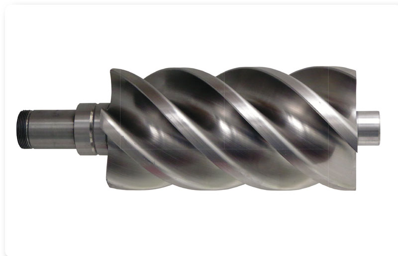 This rotor pair is characterized by two meshing, helical gears. These two rotors are differentiated by their design as male or female rotor. This position on the rotor is the line of contact. For this reason very precise manufacturing of the gearing is necessary. Otherwise a noticeable loss of power would occur.
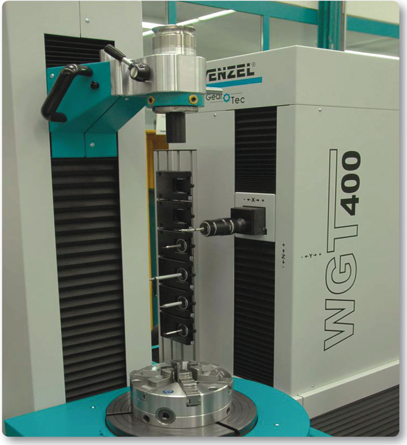
This is only one aspect of the need for reliable measurement of rotors. Measurement with a WGT series gear measuring machine from WENZEL in combination with the TRotor software module allows complete and automated analysis of these parts. The analyzing process is divided into three steps:
- Creation of the measuring program
- Measurement
- Analysis of measurement results
Fully Automated Measuring Program Creation
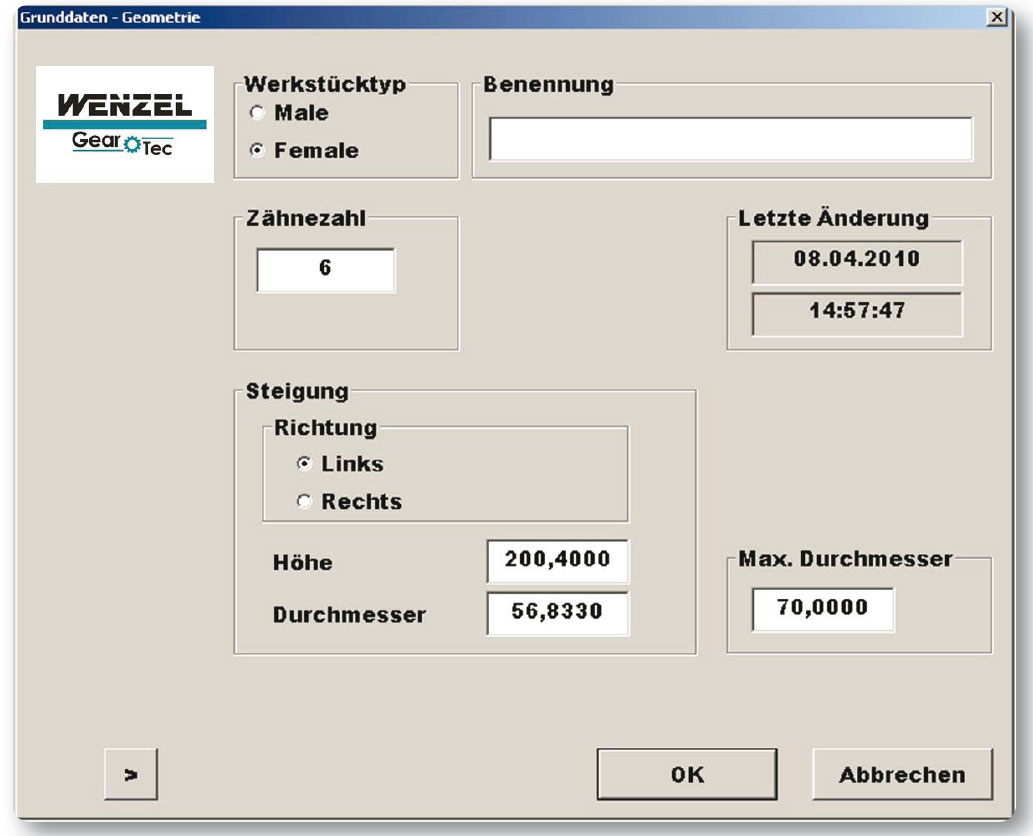 To create a measurement program the parameters of the rotor have to be entered into graphical input masks. The input mask for the geometrical data is used to enter the basis information like part type (male or female), number of teeth, direction of the lead, height and diameter. For the exact measurement definition of the lead, face width and measuring range are needed. If necessary a range for extrapolation can be defined.
For the measurement of the profile, nominal data is required. This nominal dataset is provided in a VDA format and is processed with the help of the TDatacon software module. Depending on the specification of the rotor (male or female) the data can be transformed into the specified measuring plane and the directional vector can be calculated. Form tolerances can be referred to single points, sections or the complete profile. The measuring program generation is fully automated, based upon the entered data, parameters and definitions. The measuring program is stored to a data base and can be used for the same type of part anytime. The measurement program only needs to be created once. Even if the selected range of evaluations change.
Before starting the measurement procedure the user can select different types of evaluations. This selection defines the measurement procedure. For an ideal user, guidance graphics and text can be used to support the user by clamping the part on the machine. This ensures that the part is always clamped correctly and that the measurement procedure can be carried out without any interruption.
Furthermore not only movement and measuring path are stored into the measuring program but the probe configuration used too. This probe configuration can be automatically changed with a change rack. This eliminates the manual interaction of the user and allows a user-independent, reproducible measurement. During the measuring procedure the defined profile and lead are scanned and the pitch error determined. Furthermore the parallelism of the surface line of the base circle cylinder as well as the root diameter are evaluated.
Extensive Evaluation Easily Created
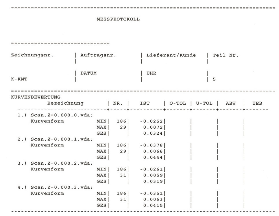 After the measurement the results are presented in graphical and numerical measurement reports. Even the creation of a statistical evaluation is possible without any considerable effort. The measurement values can be stored to a long term archive in their original form. Hence a new evaluation with changed evaluation parameters can be carried out later on.
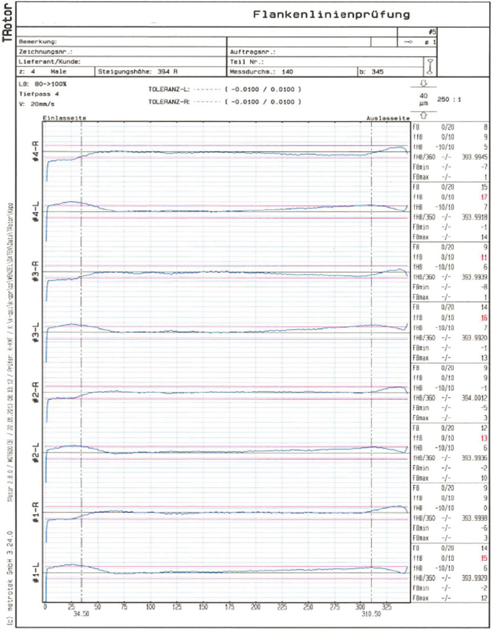 The numerical report shows the maximum deviations and the total deviation referring to the single teeth ; Also a translational and rotational best fit of the single sections can be executed. In further diagrams the lead deviations of the screw line, single and accumulative pitch errors as well as the deviations of the parallelism of the surface line of the base circle cylinder are presented.
Short Measuring and Set-up Times
When measuring a screw compressor with a WGT gear measuring machine "positive centering" of the part is possible where the rotor is fixed at the shaft centers between the centers of the tailstock. This procedure has some advantages: The measurement can be carried out without an alignment at the bearings. This shortens the measuring time noticeably. Even rotors whose bearing are not machined or maybe damaged can be measured. This allows evaluating the profile independently of a defined alignment. Based upon this measurement the machining process of the machine tool can be checked. The evaluation of profile, flank and pitch is always based on the scanned data, whether the part was aligned at the bearings or measured without alignment.
 Besides the creation of the measuring program only the definition and preparation of the probing system is necessary for this complex measuring task. Usually a single probing system is needed for the measurement. Only in exceptional cases two probe configurations are used, which can be automatically changed during the measuring procedure. This leads to negligibly short set-up times.